While in Victoria I found a RAM mount, so I screwed it to the dash so I could put both tablets up at once. That’s a Microsoft Surface Pro on the left, running Coastal Explorer, and my iPad on the right running Navionics . Coastal Explorer has a lot more features, but is kind of complex to learn, and the touch-screen interface is poor. Navionics has Active Captain built in, which I like and use a lot. The two systems complement each other, but having too many screens is kind of distracting. The Surface Pro doesn’t have a 12 volt charger, so I needed to run my inverter most of the time, and doesn’t have a built-in GPS, so that’s another wire running on the dash. The iPad looks odd because it’s wrapped in an OtterBox case. I used the iPad for almost all my navigation on this trip, and wrote blog entries and watched movies on the Surface tablet. With a 12 volt charger and a Bluetooth GPS, the Pro would be a good choice for a single computer.
June 16, 2013
June 3, 2013
AIS WatchMate Anchor Alarm
I bought the AIS to let me know what the ships around me were up to, and it works well for that, but on this trip I’ve been anchoring out almost every night and have been using the anchor alarm function. It’s given me real peace of mind each night. For instance, it was very windy last night and this morning, gusting to 30 knots, and hovering around 20 much of the time. There are boats all around me in the Nanaimo anchorage just south of Newcastle Island, and I wanted to be sure I wouldn’t drag into them.
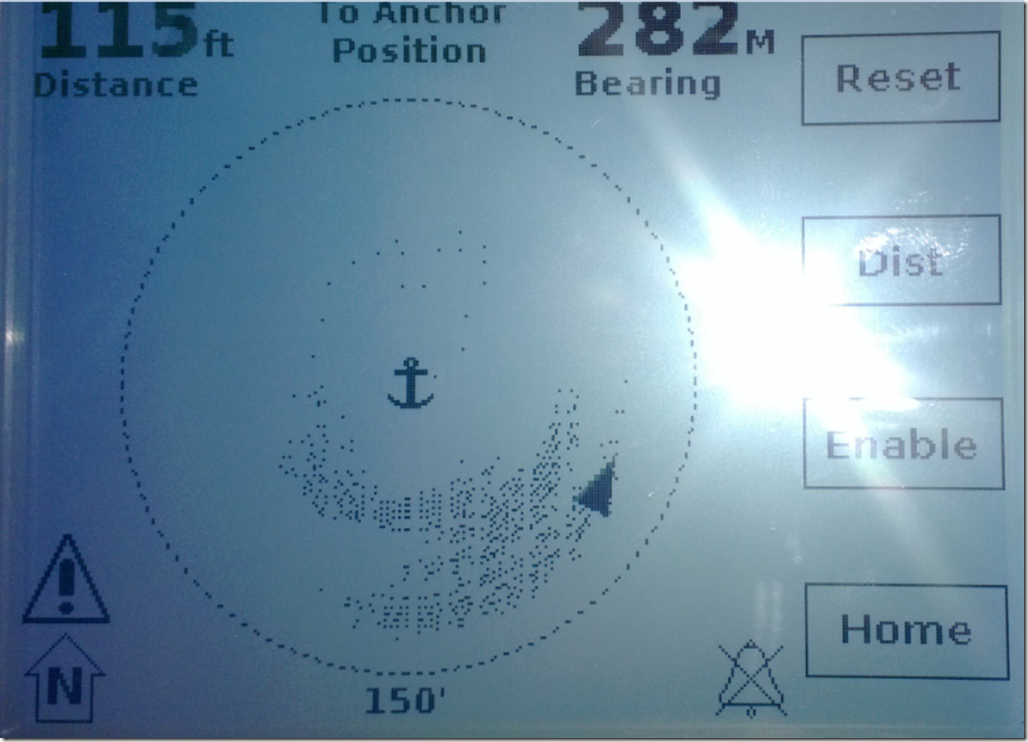
This picture shows two days of being anchored in the same place. The outer circle shows the range I can swing before the alarm goes off, in this case 150 feet diameter.. The dots are GPS positions of the boat, taken every few minutes. The inner set of dots were after I anchored, when the breeze was mild. I let out about 90 feet of line because the depth was around 25 feet. Around 2 AM the wind picked up and I increased my scope about 30 feet for better holding – which is the cluster of dots further away from the center of the circle, where the anchor is. If I had dragged about 20 feet, the alarm would have gone off.
You can tell two things from this picture – the wind is from the NNE, and the Coot swings back and forth about 30% in the wind.
May 21, 2013
SPOT Satellite Tracker
I’ve activated my SPOT tracker. You should be able to see where I’ve been on this page: http://share.findmespot.com/shared/faces/viewspots.jsp?glId=0yBWRqb2Bc25HsBrTcd1K8dgi7c4s8sRU
It doesn’t work well in IE10 – use Firefox or Chrome. Please comment here or email me if you have problems seeing the page.
Here’s my trip from Blaine to Point Roberts. It uploads a point every 10 minutes. 
March 28, 2013
Adding a Dolphin-Whacker
As part of getting ready for my Alaska trip I added a heavy bronze flat bar to the stem and first couple of feet of the bow. This is so I can run into logs or debris or even rocks without harming the boat. I bought a chunk of aluminum bronze from Online Metals, 1 1/2 “ x 5/8” x 8 feet long.
(Anyone know what this type of thing is actually called?)
I cut off an 18 inch chunk to practice with. Using the Hossfeld with a 6 foot cheater bar I succeeded in bending the part this much before giving up. It was just too hard. I had to bolt the table down to the floor and run stringers to the wall-mounted work bench because I was dragging the 400 pound steel welding table all over the shop. 
Another view. At this point I mounted a small Mat-Gas torch, pointing at the bend, and tried again when the bend got hot. The bar just broke at the heated spot. Then I got out the real piece and asked Barry to come over and help. With me leaning on the bender and Barry pulling on the stock, we got it to bend to the correct angle to run under the bow. I had made a plywood template of the bow earlier, and we used that to get the correct angle. 
Then I drilled and countersunk mounting holes, sanded off the machining marks, and rounded the top end freehand with a grinder.The lowest mounting hole is about 8 inches above waterline to avoid holes underwater. 
I mounted the thing while the boat was out of the water for a tune-up and bottom paint. The mounting holes were injected with neat epoxy to seal them. The little piece of tape is to keep it from running out. I did this a few times until the epoxy stopped being absorbed. I masked the whole area because Sikaflex wants to get everywhere! 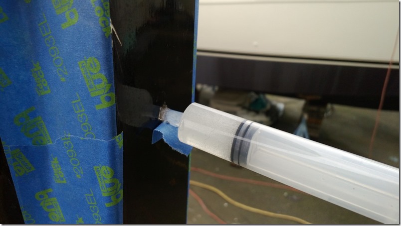
The unit was bedded in black Sikaflex. I used 8 screws, #14 x 3 1/2” bronze. 
Here she is going back in. The bronze should tarnish dark like the rest soon enough. See how the bronze wraps under the bow a couple of feet. 
April 17, 2012
Kiwi Grip Non-Skid
I finally put down non-skid on the outside decks. I’ve been meaning to do it since I launched, almost two years ago, but every time I had a nice sunny day I went boating instead of tackling this messy, uncomfortable task. It was a dumb thing to postpone so long.
I used Kiwi Grip, which is a thick, water-based paste that you trowel down and roll with a special roller to add the texture. Most of these steps would still apply when using paint with grit mixed in. I like this stuff because the texture is smoother than with grit, so it’s easier on the feet and doesn’t get quite as dirty. They say not to apply when it’s a very warm day, or in direct sun. Wash the desks before starting to tape.
Add extra tape on the edges – this stuff is messy and hard to get off if it goes outside the lines. 
Make each section a coupIe of square feet so you can do each one in one pass. I moved the cross-pieces around a few times to find a pattern I liked, using natural stopping points and dividing larger areas equally. I stood on the cabin top to make sure everything looked OK. Try to add the tape in short pieces and in reverse order of how you will fill them in, so you can easily remove the tape after each section. Have a plan on where to put the wet, gooey pieces of tape when you pull them up. A helper would have been nice. 
I sanded the large areas with 150 grip with the power sander, then used the 150 grit sanding block sponge along the edges of the tape. Get the type of block with very square corners.
With the sanding sponge, sand right up to the edge of the tape to get the little area that the tape edge protects from the sander. Try to sight from a low angle to see if any shiny spots remain. This step is important because the stuff might start peeling up along the edges if it doesn’t bond. Vacuum and wash with alcohol before starting the Kiwi Grip application. 
Application tools. Get the special roller when you buy the non-skid. I used this small-v trowel this time and was happy with the amount of material it left. Bigger grooves leave too much stuff. I applied the material right out of the can. 
Trowel it on until the grooves are very even and there are no lumps or thin spots. Scoop any remainder back into the can.
Roll and roll until the groove pattern is completely gone. Roll slowly or you will splatter. (You will spatter anyway. Carry a damp sponge to clean it up before it hardens.) Remove the tape from each section after rolling, especially if it’s a warm day. Rinse the roller after each couple of sections if it starts to load or the texture pattern will be different. 
January 14, 2012
Burgee
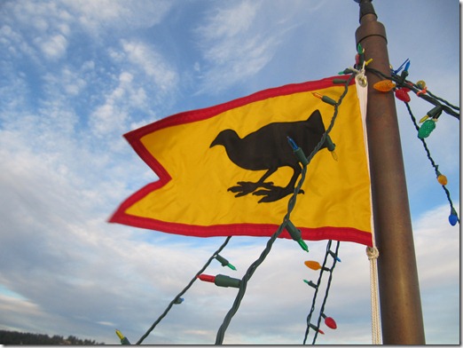
Carol Anderson made me a beautiful Coot burgee. Here it is with Christmas Lights. 
I found this quote from Lindsey Lord, so we decided to make it swallow-tailed instead of pointy: 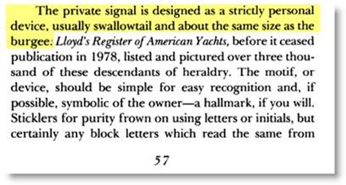
I sent her this picture. I think she did a great job translating it.
Thanks Carol!
December 8, 2010
Using an iPad as the Primary Navigation Instrument
I’m planning on using an iPad as my primary navigation tool instead of buying a standard chart plotter. To start out, all I need is a $700-$800 GPS-enabled iPad and the $50 iNavX software. I don’t need to buy the cell plan because the GPS works without it. For that price I could buy an entry-level plotter like the Garmin GPSMAP 546 or the Standard Horizon CP300i, both with substantially smaller screens than the iPad and without the advantages listed below.
I don’t like Apple’s ‘closed garden’ business model, but there’s no other tablet on the market yet with anything close to the usability of this setup, and laptop computers are a very bad fit for this. I’ve been using OpenCPN on a netbook for navigating, but the screen is too small, the keyboard is in the way, and trying to use a trackpad in a moving boat, especially in the dark, is really difficult.
There are a number of navigation applications for the iPad, but iNavX seems to have more features than the others. Here’s a short video on setting waypoints and creating a route using iNavX. The US NOAA charts are free with the iNavX purchase, and charts from X-Traverse for much of the rest of the world look reasonably priced.
I found about 20 ways to mount the iPad, but this one looks best so far. The rubber balls should soak up some of the vibration, and it’s easy to adjust, rotate, and remove the iPad. I’ll probably get two sets, one for the dash and another for watching videos below.
Advantages:
- Wireless – pick it up and use it anywhere onboard
- Take it home to set up routes and plan trips
- Huge screen – for the price, the screen is 2 to 4 times the usable size of comparably-priced Chart Plotters
- Multi-use – surf the web, play music, send emails, watch videos
- Active development of navigation apps for iPad
- Easy export of tracks to online maps
- Switch from portrait to landscape instantly
Disadvantages:
- Screen not as visible in direct sunlight as some displays, should be OK in the pilothouse
- Not waterproof without adding a cover
- No radar overlay for it (yet)
Hardware & Software:
- iPad with GPS and 3G, 64 GB: no need to subscribe to the cell plan – the GPS works without it, and the charts are store locally ($830)
- iNavX software: displays charts and shows current location. Shows data received via WiFi ($50)
- iMux WiFi NMEA multiplexer: combined information from NMEA devices and transmits via WiFi ($179)
- iAIS ANT200 Receiver: dual channel Automatic Identification System (AIS) receiver ($299)
- NMEA-Enabled Depth Sounder with display: example
- Through-hull transducer for speed and water temperature
- GPS antenna: external antenna for the AIS receiver and VHF radio (for emergency broadcast)
- iPad accessories: there are many add-ons for the iPod – chargers, keyboards, speakers, etc.
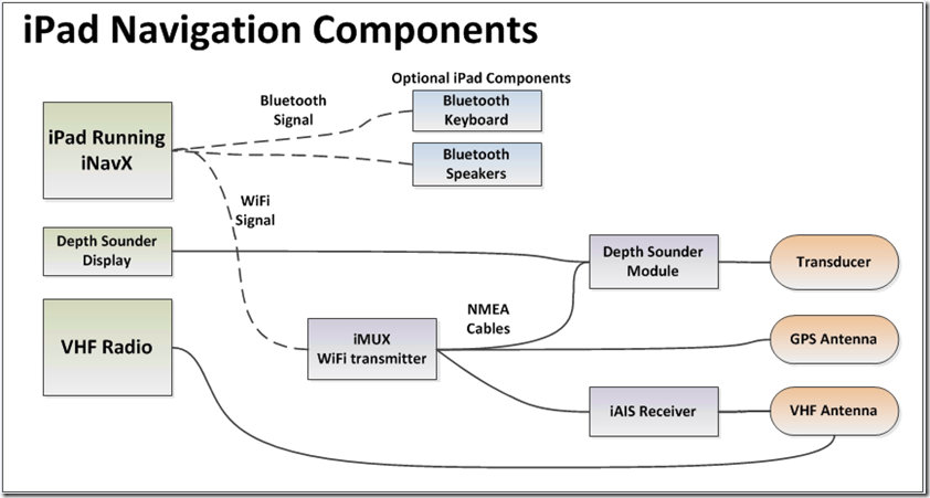
Everything in the drawing below is optional, except for the iPad itself. I can add parts as necessary.
Screenshots:
April 29, 2010
Motor Mounting
Three years ago when I was designing the outboard motor area I used my Honda 45 HP as a model. I made a full-size copy of the motor out of foam and designed the space around that. Since then I decided to use a larger motor – the Honda 60, which is the same motor as the 50 HP, but modified to put out more power. My thought being that a 50 horse motor should probably be about the same size as a 45 horse motor. Not exactly.
The new motor is quite a bit deeper fore and aft, and wider than the old motor. I made the well 18 inches wide, which is almost 4 inches wider than the old motor needed. The new motor only swung about 25 degrees before hitting the sides. It’s supposed to swing 30 degrees. I’m guessing this is a bad thing. To be honest, I kind of planned for this way back when I was building this area – I assembled the sides of the well without fasteners in case I had to cut them down, which is exactly what I’m doing now.
So far I’ve cut out the starboard side so the motor will swing 29 degrees. I’ll finish the cutout this weekend so it will get all the way to 30 degrees, and then do the other side. I was really concerned that I’d end up cutting through the side into the space under the sole, but it looks like I’m safe from that. The finished area is going to look kind of, um, interesting, but I think it should work OK.
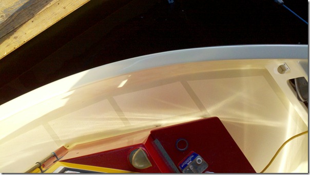
Here’s the area we’re talking about. The motor is in the neutral position in this picture. I bought the big plastic protractor and am marking the angles on the blue tape. 
The starboard-side cutout so far. I’ve removed a lot of wood, but it’s not structural. 
And the motor nested into the cutout. At this point it can swing 29 degrees – just a little more to remove to hit 30 degrees.: 
April 18, 2010
Unboxing the Honda
The box the motor came in was huge – as wide as the truck bed between the wheel wells, and so long I couldn’t close the tailgate. They loaded it with the help of three guys and a forklift. I was a little concerned about what I would do with it when I got it home. The motor weighs 250 pounds, and the box added at least 50 more.
I opened up the rear of the tent and realized it wasn’t going to fit in the space I had allocated for it, so I had to dismantle my glassing station , and I took the time to drag the old refrigerator to the dump. The fridge had been used to keep my epoxy warm in the winter – I punched a hole in the side and ran a small light inside. It had worked great, but I was done with it.
I slid the box out onto cushions and a couple of empty kitty litter boxes. The boxes crushed in slow motion when the motor landed on them, lowering the motor slowly to the cushions. 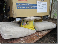
Inside the cardboard box was a welded steel frame, bolted together. The motor mount was bolted to the frame, and encased in molded foam. A very professional packing job! 
I carefully unbolted everything and moved the motor onto a dolly I made for the purpose – just 4 casters and a sheet of plywood. The motor head is on a cushion . Meryll came out to see if I’d crippled or killed myself yet. 
I went to Home Depot and bought a 12′ foot 2×8 and ran it across the tent above the stern of the boat where the motor needed to go, and made a little truck out of 3 small casters and plywood to ride on top of the beam. Then I rolled the dolly to the right spot and winched the motor up until it was standing up. The motor has 2 steel hanging loops built in, just for this task. 
Unfortunately, the tent is too low for me to just lift the motor over the side of the boat, so I raised it as high as I could and then lifted the lower unit up over the gunnel. I rolled the truck toward the center of the boat, and lowered the thing into place. The lines are just a safety measure, in case the truck spontaneously disassembled itself. 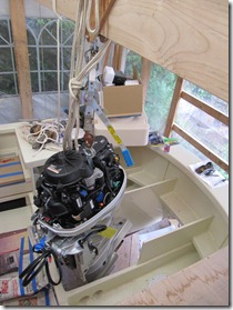
Lowering the motor into place, I realized the boat was too low for it to go down all the way so I cut out a chunk of the floor for the bottom of the motor to drop into. 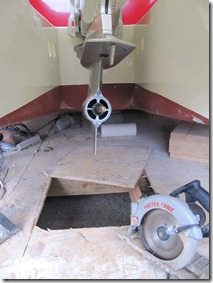
I clamped the motor mount into place and drilled the four mounting holes, the moved the motor out of the way to coat the holes with neat epoxy. Tomorrow I mount the thing! 

